1. Theory of circuit analysis
1.1. Basic laws
The methods of the circuit analysis are based on Ohm's law and Kirchhoff's laws. These laws were originally based on experiments, but they can be derived from Maxwell's equations, too.
1.1.1. Ohm's law
Ohm's law states that a current ( I ) flowing in a circuit is proportional to the voltage ( U or V. In this webpage U is used for Voltage)
R is a constant called Resistance ( 'R' ), its measurement unit is 'volt per ampere', or 'ohm' [Ω]
1.1.2. Kirchhoff's circuit laws
Kirchhoff's first law or Kirchhoff's junction rule expresses the conservation of the electric charge: the sum of charges (or currents) flowing into a node or any part of a circuit is equal to the sum of charges (or currents) flowing out of it. If we declare every current directions into the node as positive, then Kirchhoff's first law has this formula:
Kirchhoff' second law or Kirchhoff's loop rule expresses the voltage equilibrium of a loop: it states that the directed sum of electrical potential differences (voltages) in a closed circuit is zero:
1.2 Methods of circuit analysis
1.2.1. Combined method
In this method we use Kirchhoff's circuit laws for analyzing the circuit. When using this method, the currents in the branches are unknown, and we write the equations using junction rule and loop rule. Let's take this example circuit:
The
number of independent equations is the number of nodes minus one. On
the above picture the equations based on Kirchhoff's first law
in
the A, B, C nodes:
A:
B:
C:
I:
II:
III:
1.2.2. Other methods
The main disadvantage of the combined method is that to get the results you have to solve many equations, which is very time-consuming, and without the help of a computer it's very easy to make a mistake. Because of this disadvantage many alternative methods have been developed, which are based on Kirchhoff's laws and the combined method, but require fewer equations.
Some of these methods are nodal analysis, mesh analysis, or equivalent transformations. These methods can be found in the books, or on other relevant internet pages. This program doesn't use these methods, because in most cases they require human intuition, which is hard to put in a computer programme. The other reason is, that these methods require some prerequisites, which cannot be fulfilled in every case.
1.2.3. Method of this programme
2. Storing the circuit's data
The circuit is made of display nodes (points) and components (resistance, voltage generator, current generator, wire). Circuit nodes can be placed only to the nodes of the screen, and components can be placed only between two nodes. Because the graphical display should be unambiguous, there can not be a node on the line connecting the two ends of a component.
The "Point" class stores the place of the points (nodes of the display grid, but not necessary nodes of the circuit) and the information and procedures needed to display it.
As excluding the analysis, the exact drawing and the dimensions, there's no difference among components, every component classes ("Wire", "Resistance", "VoltageGenerator", "CurrentGenerator") have the same base class "Section".
The "Section" class stores, which are the end points of a section, what is its numeric value, dimension, its name and direction. It also stores information on graphical display, and does part of it. (which is common to every component, like name) The exact drawing of a component is done by the child classes ("Wire", "Resistance", "VoltageGenerator", "CurrentGenerator")
The "Circuit" class has a "points" and a "Sections" array. It has procedures for adding and deleting points and components. It handles the commands made by the mouse, and after giving a proper command it fulfils the adding or deleting procedure. The actual function of the mouse can be determined by using the control panel.
3. Analysis
The process of the analysis is as follows:

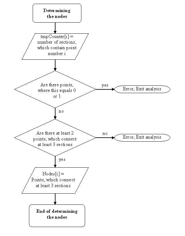
3.1. Determining the nodes
That display node (point) can be considered as a circuit node, which connects at least 3 sections. Which connect only 2 is nothing else but a connection of 2 components, and creates a single branch. The case when a point has only 0 or 1 connection is an error. If there aren't at least 2 nodes, that's an error, too.
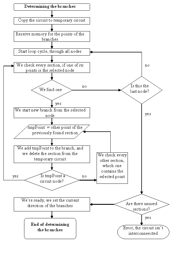
3.2 Determining the branches
After determining the nodes, the branches have to be found. A branch is always between two nodes.As a first step, we make a copy of the circuit. Then we pick one point, which is a node in the original circuit.
We pick one section starting from the point, and if it isn't a node, we pick the continuing section, etc. We continue doing this, and soon we get to a point which is a node. These sections constitute a branch.
At this point we delete the whole branch from the temporary copy or the circuit, and continue this process. At the end the remaining circuit is empty, and we have all the branches we wanted.

3.3 Determining the loops
For the loop-equations we have to determine the loops. The first thing to do is to copy the circuit to a temporary copy, and remove the current generators, as they cannot be part of a loop-equation.
Then we remove those remaining components, which now, as we removed the current generators has only one connection to the circuit. We pick a section, then an other one, which connects to this one, and we continue this process. We stop when we reach to a point, which has already been selected before. This isn't necessary the first point, at this figure below shows: here we started form point "A", but the "circle" ends in point "C".
We skip those sections, which aren't part of the loop (on the figure AB and AC). The loop contains original circuit nodes, so we can determine which branches make the loop.
The next step is to remove one of the branches from the temporary circuit, and ten remove those sections, which aren't connected to the circuit with their both sides. We continue this process to the end. As we always removed a branch, which was part of the actual loop, this way we ensure, that the selected loops are independent.

3.4 Determining and solving the equations
As now we have the nodes and the loops, we can set the equations. To these we add those equations, which state, that the current in a branch with a current generator equals with the generator's currentIn this program we write the equations in a matrix and solve it with Gaussian elimination.
